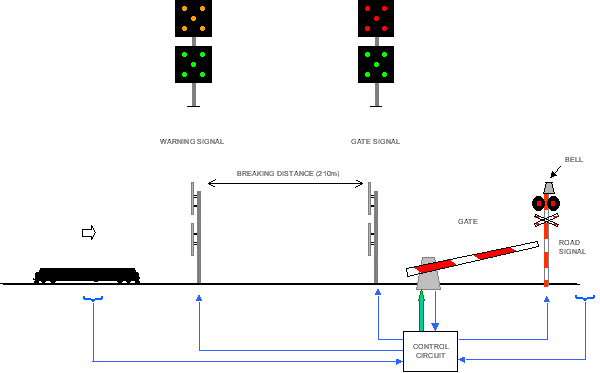
| Gate barrier protects the level crossing. In the color
light area gate barriers are automatically operated when a train
approaches it from either direction. The gate machine has 110V d.c. motor
to operate the gate. It also consists of contacts to get indication of the
status of the gate. The figure below illustrates a gate barrier system.

The gate barrier has two signals on the track on either side of the
road. The signal at the distance is called an early warning. It has
two aspects of amber and green. The five lamps are arranged in a manner to
represent letter "W" for Warning. The amber aspect means the
gate is not protected. This signal is located at a distance to allow the
driver of the train to apply brakes and stop the train if necessary. The
green aspect means the gate is protected and the train can pass the gate
at its normal speed. The signal near the gate has a similar arrangement;
red on top unit and green on lower unit. If the gate is protected the
green aspect will be lit and if not the red.
The gate barrier system also has flashing two unit warning signals on
either side of the track for the road traffic. A warning bell is also
fixed on the mast. It rings before and while the gate is closing. The
circuits are wired in such a manner a failure on the gate motor circuit
will result in the continuous ringing of the bell. In such an occasion the
gate-man will inform this to the nearest station master using the gate
telephone and he in turn will inform the STI. |