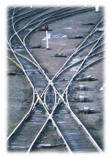
| Point is a place where the track branches off. The points
can be either manually switched (lever frame) or motor driven. Most of the
points in the color light area are motor points and can be controlled by
the Maradana control office.
 The point motor is powered by 110V d.c. supplied by the nearby relay
house. When an order is given to switch the point, power is given to the
motor in the respective direction. The motion is used to either push or
pull the drive rod. Point machine has contacts for detection of the
switching. These contacts are operated by the long and short detection
rods. When the point is set properly an indication is obtained by the
relay house through these contacts. The allowable gap between the stock
rail and the switch blade is 3mm. When a foreign material such as a stone
prevents the point from setting properly, the indication contacts stay
neutral and no indication is sent. The clutch mechanism in the point
machine will start slipping in order to protect the machine from
mechanical damages. The safety relay attached to the motor circuit will
cut off power in 15 seconds. When no indication is obtained at the control
office, the controller will inform the Signal and Telecommunication
Inspector (STI) in charge of the respective yard. On receipt of the
information, STI will go to the motor point in question and remove the
obstacle. The point machine has a facility to operate it by manual cranking.
Once the point is cranked, the operation is finished and the indication
will received by the control office. The point motor is powered by 110V d.c. supplied by the nearby relay
house. When an order is given to switch the point, power is given to the
motor in the respective direction. The motion is used to either push or
pull the drive rod. Point machine has contacts for detection of the
switching. These contacts are operated by the long and short detection
rods. When the point is set properly an indication is obtained by the
relay house through these contacts. The allowable gap between the stock
rail and the switch blade is 3mm. When a foreign material such as a stone
prevents the point from setting properly, the indication contacts stay
neutral and no indication is sent. The clutch mechanism in the point
machine will start slipping in order to protect the machine from
mechanical damages. The safety relay attached to the motor circuit will
cut off power in 15 seconds. When no indication is obtained at the control
office, the controller will inform the Signal and Telecommunication
Inspector (STI) in charge of the respective yard. On receipt of the
information, STI will go to the motor point in question and remove the
obstacle. The point machine has a facility to operate it by manual cranking.
Once the point is cranked, the operation is finished and the indication
will received by the control office.
Some points in the color light area are of lever frame type. They are
not frequently switched during routine operations. These type of points
are protected by a device called "magnetic lock", which has to
be released by the controller at the central office to enable station master
to switch the point. After the operation is completed station master
will switch the point back to its normal position and it is locked by the
controller. This ensures that all the points are under the controller at
the central office. |